Building an Altairduino, part 2
On your marks
Like all projects, you can't get started until you have the things you need. The shopping list for David Hansel's Altair simulator wasn't huge, and some of the items such as LEDs and resistors I already had.
However I decided to buy everything, including things I already had, so that I'd have some uniform-looking LEDs rather than mixing and matching (there are 36 LEDs required in total). For the whole lot it came to just over £100 at Mouser, including the Arduino Due which on its own was almost half the total cost. I could probably have reduced the cost a little by ordering from one of the well-known Chinese electronics suppliers, but you can never be 100% sure about quality.
All the bits duly arrived at my door in a big cardboard box, and I was just waiting for an opportunity to get started.
Get set
One of the first issues I had to resolve was what would the computer's case be made of? I have zero skills or experience in metalworking, I don't own a 3D printer, and although I have some basic knowledge of woodworking I don't have many of the required tools these days.
In the end I decided to put off the question of making a case until later, and came up with a very simple way of creating the prototype.
I downloaded this image of the Altair front panel and printed it in colour as large as possible on some A3 paper. I then bought a sheet of heavy A3 card from my local craft shop and sellotaped (yes, sellotaped!) the Altair front panel image to it.
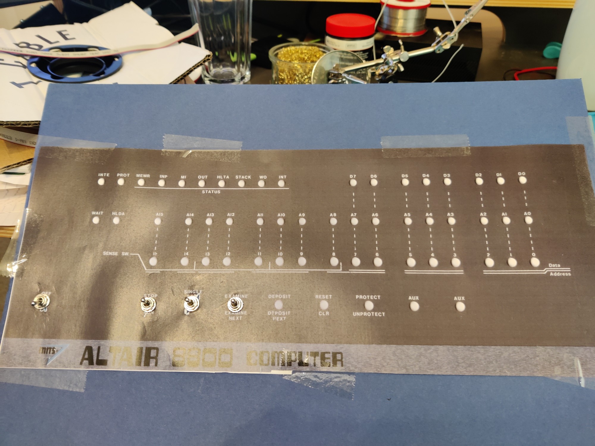
Yes it's simple and basic but it's quick and easy to do and once I've put everything together and confirmed it all works, it will be easy to disassemble once I've found a more permanent solution.
Go!
I've got the parts, I've worked out how to make a basic copy of the front panel, let's get building!
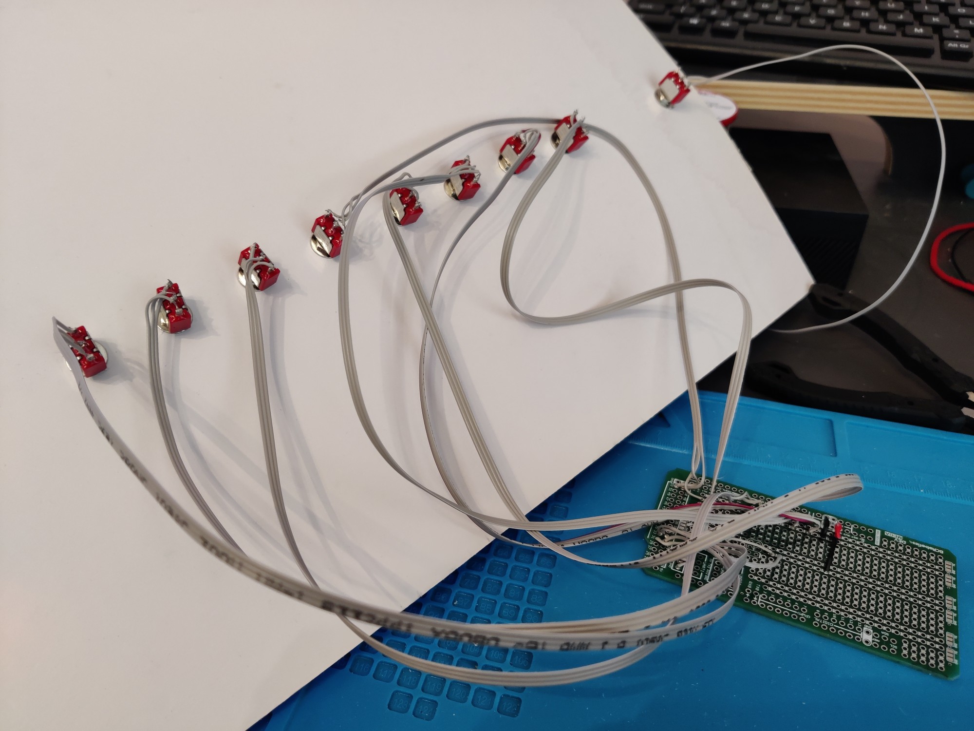
To start with I have simply soldered some ribbon cable to the switches, mounted them in the card front panel, and at the other end soldered them to an Arduino Due shield.
Here's what it looked like from the front and back, after doing a couple of the switches:
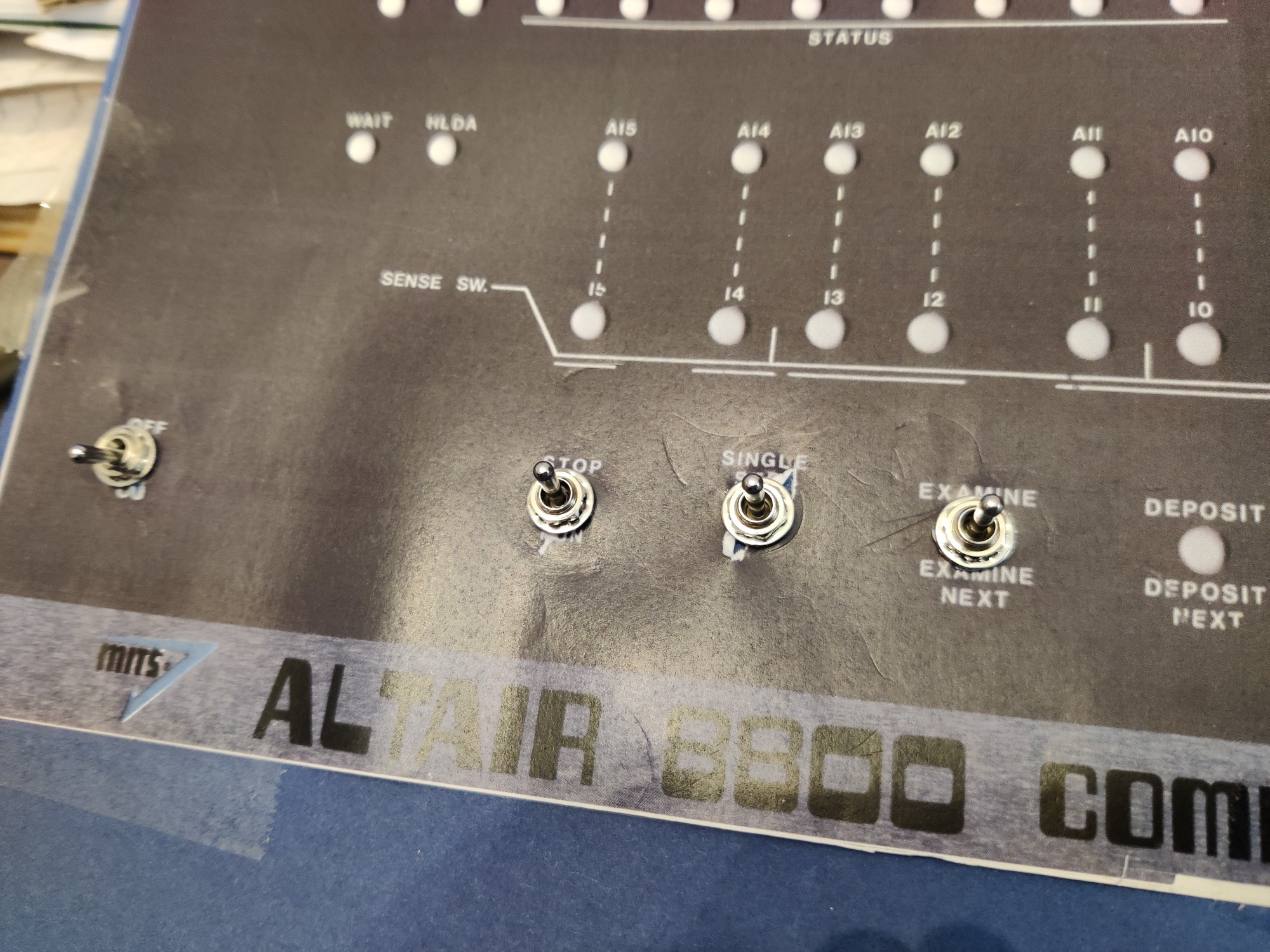
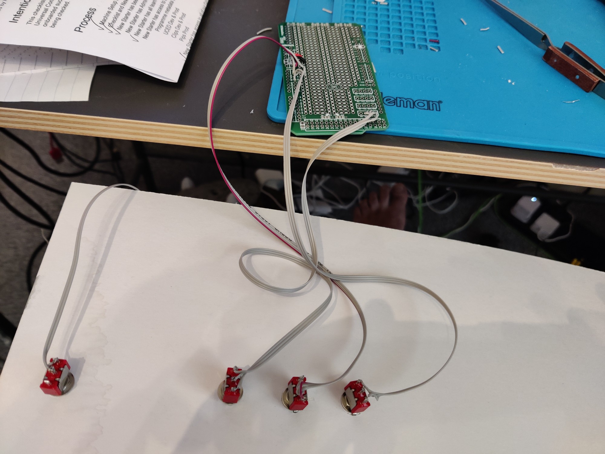
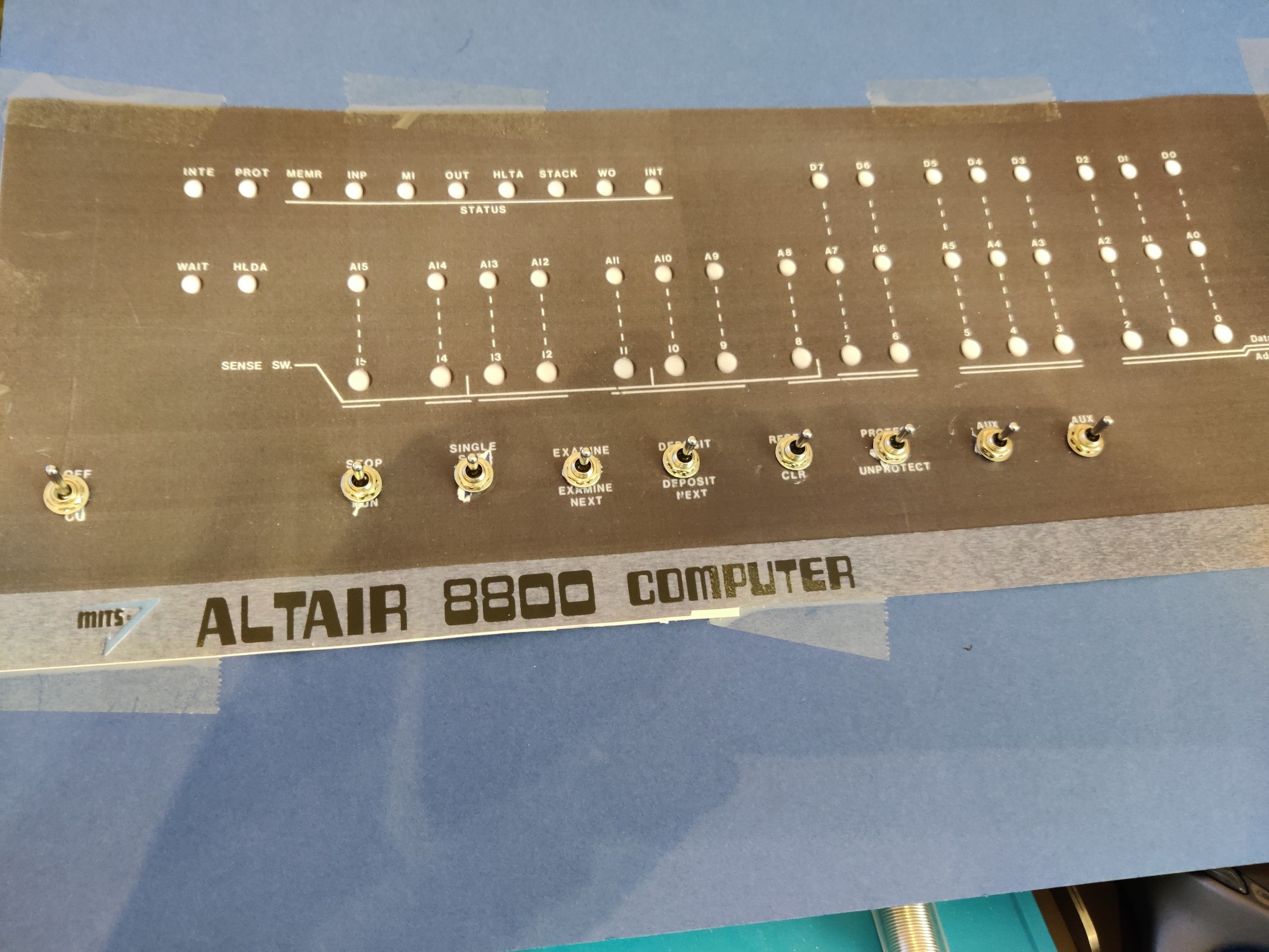
An hour or two later and I had all the function switches cabled up:
Below is a close up of the shield at this point. I chose to use a shield for a couple of reasons. One was simple practicality: the only Arduino Due I could find already had female headers soldered on. So in order to do anything sensible with it I could either painstakingly unsolder all of those headers, or (slightly less painstaking) solder my own headers to the shield and pop it on top of the Arduino.
The other reason is that it's a lot easier to solder onto the shield due to having plenty of additional solder points. Every switch needs a connection to ground, every LED needs a connection to Vcc, and the shield comes with lots of rails that can be used to give me plenty of places for those connections.
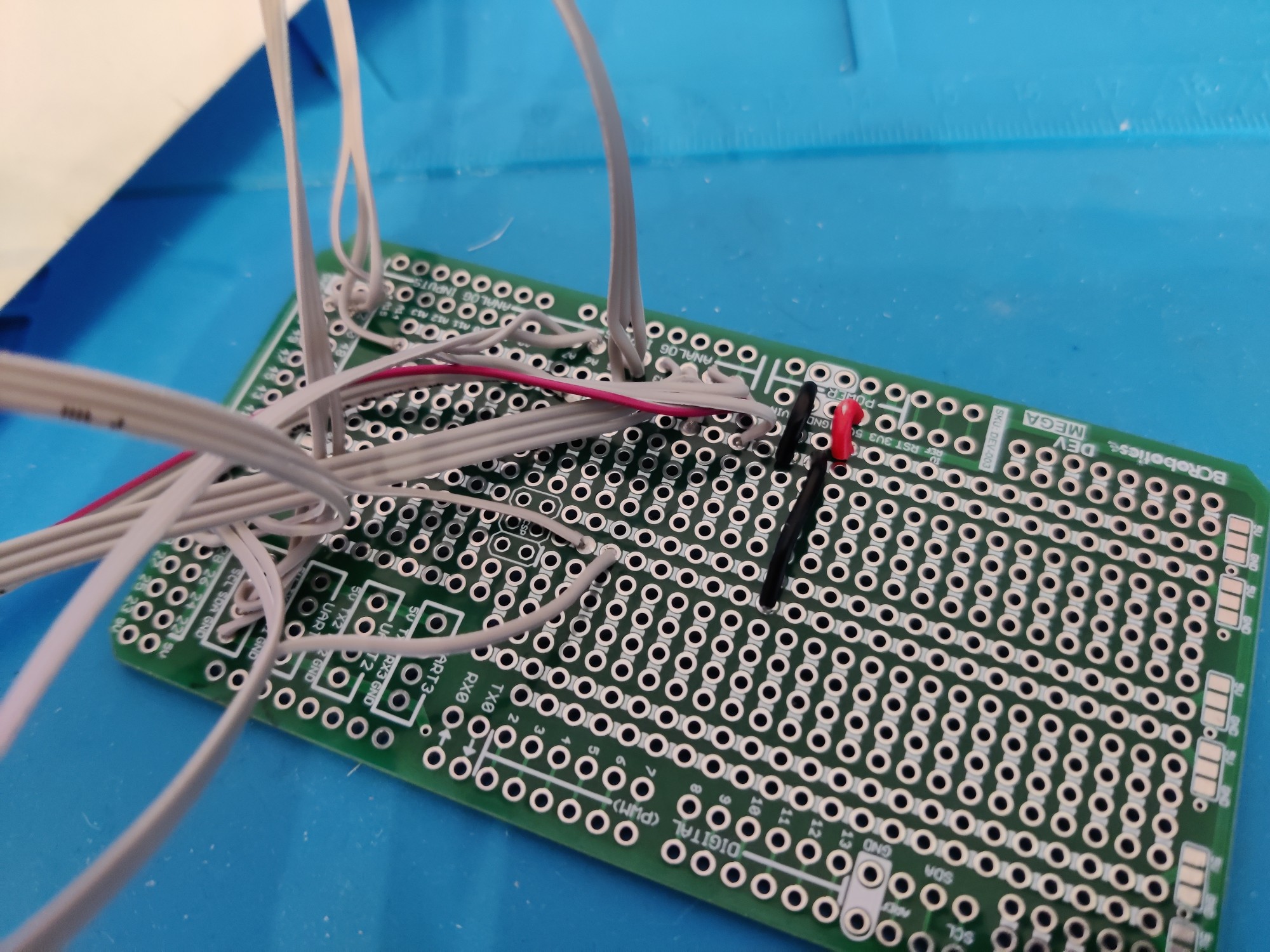
This is as far as I've got so far. Next step is continue soldering up the data switches — there are 16 on/off toggle switches required although at least they each only need two pins connecting as I'm using a Due which has pull-up resistors built in.